What model of Saab are these in?
Are they worth a try?
any of the turbo saabs from mid 80s to early 90s before they integrated it into the trionic ECU and did away with the knock sensing.
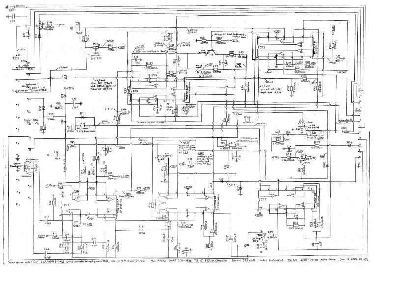
these are the schematics for the newer 25 pin variant: (they're big pics)


i started reverse engineering the redbox one i have before i found those.
basically, the stock boost pressure sensor is a resistive unit, that provides 1/2 of a voltage divider. the F pot and another 909 ohm resistor pull voltage to a 7.35v reference, and as the pressure increases, the resistence of the sensor increases, pulling the voltage further from ground. the voltage range tops out around 650mV. you can see that the reference voltage used on IO2a (opamp wired as comparator) is 618mV (voltage divider comprised of R35 and R46), so the output goes high and the F-circuit controls boost whenever the boost signal exceeds that value. also note that the rpm signal from the LM2907 on the smaller board is fed into this as an averaging circuit via R138 and R37. as RPM increases, this pulls the boost value higher, which is what tapers the boost off. i've read that folks who have tried to remove this feedback have experienced "unstable boost," but i don't have any more info than that- whether they mean that it fluctuates, rises, falls, or what. the RPM signal could also be fed into the reference voltage to prevent tapering and an RC filter on the output of IO2a could help if the circuit oscillates too badly.
pin 24 can be connected to a powered LED that will light whenever the F-circuit is controlling boost, and pin 11, when held to ground, will disable the F-circuit and the unit will only use the P circuit to control boost. i'm assuming this function is to disable F while setting P.
pin 19 can also be connected to a powered LED and will light the LED whenever knock is detected.
to use a normal MAP sensor, the signal would have to be attenuated to a slope whose peak is slightly above the 618mV reference (via potentiometer or opamp) and fed into R41 while disconnecting the rest of the input side of the F circuit.
i'm still trying to get a handle on how the P circuit works.
pin 18 is the internal knock signal. it begins to amplify the signal once input voltage starts to get to around 4V, but it limits the signal below that. i think as long as you have a knock sensor that's tuned to ring at the knock frequency of your block, this will work for any engine, since it's the amplitude it's looking for rather than frequency.
the 2907 produces a reference voltage to weed out noise at higher rpm.
locations on the cars varies. there's a lot of info here:
http://www.900aero.com/applications/phpBB/viewforum.php?f=7&sid=93385c61219531772e07599fc1ade3ae Author
Topic: anyone using a saab APC as an RHMT boost controller? (Read 23814 times)


