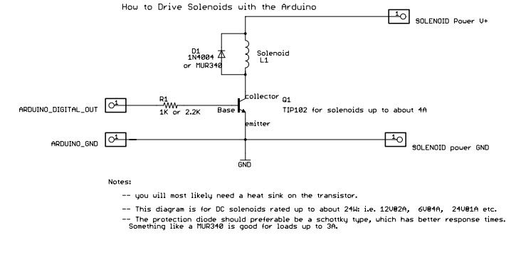
I posted this on another forum and got no responses. Maybe you guys can make some use of this!
I have been messing around with building my own EBC now that MAC valves are becoming very cheap. I am in brainstorming and design phase of this project but I thought it would be cool to share what I have so far. I do not have too much time invested in this so do not be shocked if this is rough so far.
Found a hardware diagram that will work PERFECT for this project. I have already simulated this circuit and tested it for feasibility with standard MAC solenoids used (AEM, Hondata, Neptune, eCtune, ect) and it looks good.

Hardware needed would be the driver circuit above, arduino, solenoid, potentiometer and to do something about voltages. No biggie.
Here is the code I busted out really quick. This is not tested so be surprised if it does not work!
// DSMR Boost controller concept code

void setPwmFrequency(int pin, int divisor) {
  byte mode;
  if(pin == 5 || pin == 6 || pin == 9 || pin == 10) {
    switch(divisor) {
    case 1:
      mode = 0x01;
      break;
    case 8:
      mode = 0x02;
      break;
    case 64:
      mode = 0x03;
      break;
    case 256:
      mode = 0x04;
      break;
    case 1024:
      mode = 0x05;
      break;
    default:
      return;
    }
    if(pin == 5 || pin == 6) {
      TCCR0B = TCCR0B & 0b11111000 | mode;
    }
    else {
      TCCR1B = TCCR1B & 0b11111000 | mode;
    }
  }
  else if(pin == 3 || pin == 11) {
    switch(divisor) {
    case 1:
      mode = 0x01;
      break;
    case 8:
      mode = 0x02;
      break;
    case 32:
      mode = 0x03;
      break;
    case 64:
      mode = 0x04;
      break;
    case 128:
      mode = 0x05;
      break;
    case 256:
      mode = 0x06;
      break;
    case 1024:
      mode = 0x7;
      break;
    default:
      return;
    }
    TCCR2B = TCCR2B & 0b11111000 | mode;
  }
}
long previousMillis = 0;
long interval = 1;
void setup() {
  setPwmFrequency(10, 1024);
}


void loop() {
  unsigned long currentMillis = millis();
  if(currentMillis - previousMillis > interval) {
    previousMillis = currentMillis;
    int DC = analogRead(0);
    DC = map(DC, 0, 1023, 0, 100);
    analogWrite(10, DC);

  }
}
I will update this later on if I get a chance to work on it. Code is kind of tricky and requires some massaging of a few timers. I calculate it to be at ~31hz but will check with an O-scope to verify.
What is next: All I need to do is program a board with this code and check it with an o scope. I will use the potentiometer to change duty cycle.
Once that is checked and works like it should, I will build the high side of the circuit and check to see if it makes some clicky clack on the solenoid while I check all voltages with o-scope and multimeters.
If all of that works it will be tested with shop air for a proof of concept. If that works all that is left is packaging. Its that easy.
For the over achievers, this would be a perfect foundation for someone to make a fancy boost controller that uses some PID trickery to home in on a selected boost pressure. MAP sensors are cheap cheap cheap! I won't be doing any of that. The only reason I am making this is because I am lazy and am tired of getting out of the car to tweak manual boost controllers on cars that I tune (and its cold outside).
 Author
Topic: Electronic Boost Controllers (Read 33201 times)


