just thought i'd throw this up here...
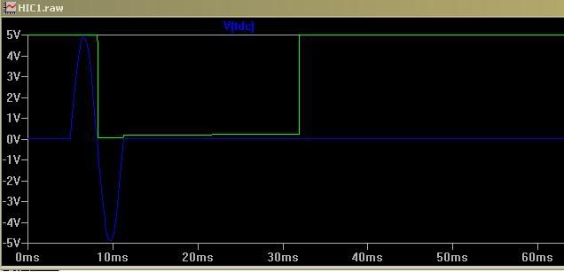
since i don't have a scope, i drew the TDC signal conditioner circuit on the HIC1 board in LTSpice and ran it through a simulation with a sine wave input.

if you're working on getting a honda ECU to run on another distributor, you'll notice that the rising edge of the signal is the one that corresponds with the zero-crossing portion of the wave (i.e. tooth lined up with sensor). the output signal of the HIC1 is inverted before it's sent to the MCU (so the MCU is a falling edge trigger).
if you try to drive it with a signal that goes positive first (most other distributors), the output pulse width is really wide, and can potentially stay high long enough to miss the next tooth at high rpm:

either way, it should be pretty easy to run almost any distributor provided you can get the reference edge correct, and use the right logic to get all 3 signals.
i'd really like to check what toyota uses for signal conditioning for their ECUs, but i sold my stock one. i'll have to see if i can swipe another one locally for a day to pull a schematic from the dizzy inputs.
 Author
Topic: First RHMT Turbo Geo Prizm. 56k go find a sock. (Read 57973 times)


